SMART FACTORY
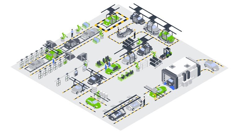
AUTOMOTIVE INDUSTRY

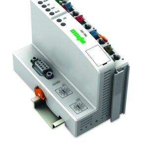
| Communication | PROFIBUS |
| Visualization | none |
| CPU | 16 bits |
| Programming languages per IEC 61131-3 | Instruction List (IL) Ladder Diagram (LD) Function Block Diagram (FBD) Continuous Function Chart (CFC) Structured Text (ST) Sequential Function Chart (SFC) |
| Programming environment | WAGO-I/O-PRO V2.3 (based on CODESYS V2.3) |
| Configuration options | GSD device description file WAGO-I/O-CHECK |
| Cycle time | < 3 ms for 1000 bit instructions/ 256 digital I/O |
| Baud rate (communication/fieldbus 1) | 9.6/12 MBd |
| Baud rate | 9.6/12 MBd |
| Bus segment length (max.) | 1200 m |
| Transmission medium (communication/fieldbus) | Cu cable per EN 50170 |
| Transmission time | typ. 1 ms (10 controllers; each 32 digital I/O and 12 Mbaud) max. 3.3 ms |
| Number of fieldbus nodes on master (max.) | 96 |
| Number of I/O points | 6,000 |
| Program memory | 128 KB |
| Data memory | 64 KB |
| Non-volatile software memory | 8kbyte |
| Memory for fieldbus input variables (max.) | 244Byte |
| Memory for fieldbus output variables (max.) | 244Byte |
| Number of modules per node (max.) | 63 |
| Number of modules without a bus extension (max.) | 63 |
| Input and output process image (fieldbus) max. | 244 bytes/244 bytes |
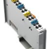
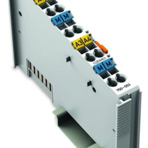
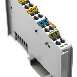
| Indicators | LED (RUN) green: Fieldbus initialization, LED (BF, DIA, BUS) red: communication error, external diagnostics, configuration; LED (I/O, USR) red/green/orange: Local data bus status, status programmable by user; LED (A, B) green: System power supply status, field supply |
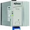
| Supply voltage (system) | 24 VDC (-25 … +30 %); via pluggable connector (CAGE CLAMP® connection) |
| Input current (typ.) at nominal load (24 V) | 500mA |
| Power supply efficiency (typ.) at nominal load (24 V) | 87% |
| Current consumption (5 V system supply) | 200mA |
| Total current (system supply) | 1,800mA |
| Supply voltage (field) | 24 VDC (-25 … +30 %); via power jumper contacts |
| Current carrying capacity (power jumper contacts) | 10A |
| Number of outgoing power jumper contacts | 3 |
| Isolation | 500 V system/field |
| Standard | EN 50170 |
| Connection technology: communication/fieldbus | PROFIBUS: 1 x D-Sub 9 socket |
| Connection technology: system supply | 2 x CAGE CLAMP® |
| Connection technology: field supply | 6 x CAGE CLAMP® |
| Connection type 1 | System/field supply |
| Solid conductor | 0.08 … 2.5 mm² / 28 … 14 AWG |
| Fine-stranded conductor | 0.08 … 2.5 mm² / 28 … 14 AWG |
| Strip length | 8 … 9 mm / 0.31 … 0.35 inches |
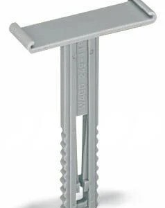
| Connection technology: device configuration | 1 x Male connector; 4-pole |
| Width | 50.5 mm / 1.988 inches |
| Height | 100 mm / 3.937 inches |
| Depth | 71.1 mm / 2.799 inches |
| Depth from upper-edge of DIN-rail | 63.9 mm / 2.516 inches |
| Weight | 186.9g |
| Color | light gray |
| Housing material | Polycarbonate; polyamide 6.6 |
| Conformity marking | CE |
| Ambient temperature (operation) | 0 … +55 °C |
| Ambient temperature (storage) | -25 … +85 °C |
| Protection type | IP20 |
| Pollution degree | 2 per IEC 61131-2 |
| Operating altitude | without temperature derating: 0 … 2000 m; with temperature derating: 2000 … 5000 m (0.5 K/100 m); 5000 m (max.) |
| Relative humidity (without condensation) | 95% |
| Mounting position | Horizontal left, horizontal right, horizontal up, horizontal down, vertical top and vertical bottom |
| Mounting type | DIN-35 rail |
| Vibration resistance | 4g per IEC 60068-2-6 |
| Shock resistance | 15g per IEC 60068-2-27 |
| EMC immunity to interference | per EN 61000-6-2, marine applications |
| EMC emission of interference | per EN 61000-6-4, marine applications |
| Exposure to pollutants | Per IEC 60068-2-42 and IEC 60068-2-43 |
| Fire load | 3.002MJ |
| Permissible H2S contaminant concentration at a relative humidity 75 % | 10ppm |
| Permissible SO2 contaminant concentration at a relative humidity 75 % | 25ppm |

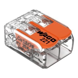
Cầu Đấu Dây
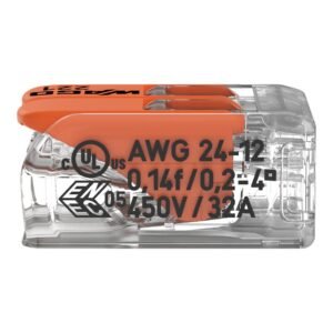
Cầu Đấu Dây
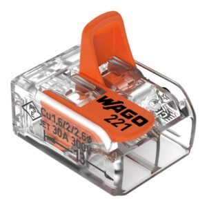
Cầu Đấu Dây
Cầu Đấu Dây
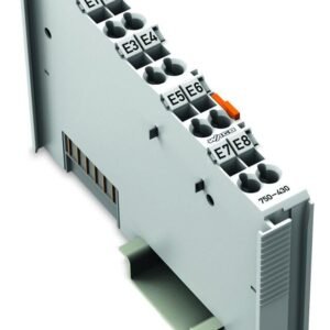
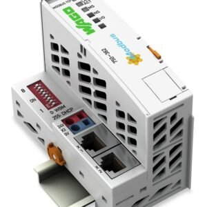
Hệ Thống I/O
Cầu Đấu Dây
Cầu Đấu Dây
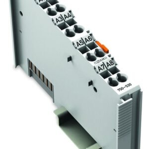
Hệ Thống I/O
Cầu Đấu Dây
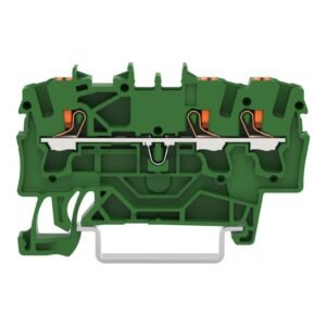
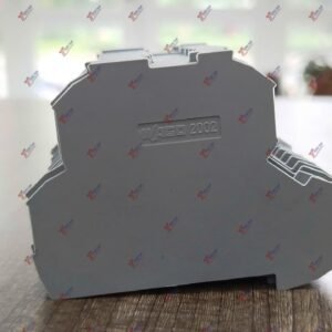
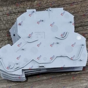
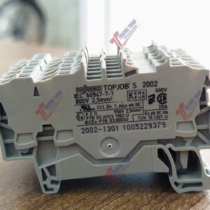
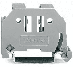
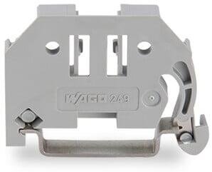
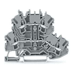
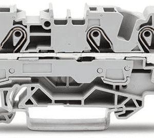
Rail-Mount Terminal Blocks
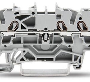
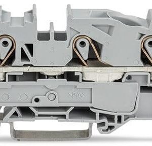
Item no. 2202-1301/000-001 3-conductor through terminal block
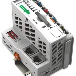
Bộ Điều Khiển PLC
Cầu Đấu Dây
Hệ Thống I/O
Cầu Đấu Dây